| The last frame was ==>... | The End Effector |
...and the next frame will be ==>... | The PCBs |
|---|
The robot Z is the primary component of the autoloader's robot subassembly. At the completion of this section, you will be able to describe, in detail, the function and purpose of the robot Z subassembly and its component parts.
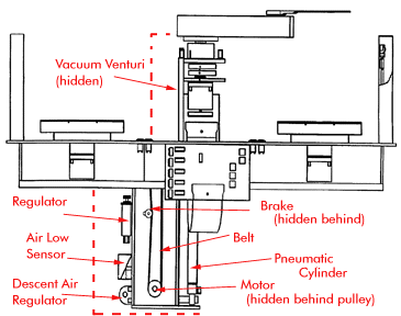
The robot Z elevator subassembly is responsible for moving the robot assembly
vertically. The housing for the motor gear shafts of the end effector and shoulder
motors is mounted to the robot Z.
Components
The robot Z subassembly consists of:
Z brake 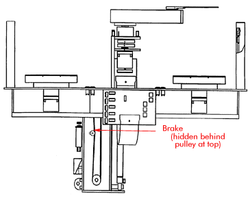
Releases and allows movement of the drive belt when signaled by the PCB.
Robot Z flag and sensors 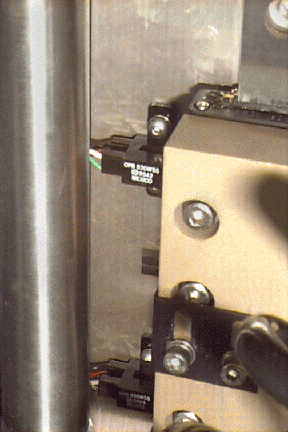
Provides position verification of robot Z critical positions--home, TP0, and TP1.
Air low sensor
Signals up and down and air pressure.
Pneumatic assist assembly (Air pressure regulator, cylinder, descent
air regulator)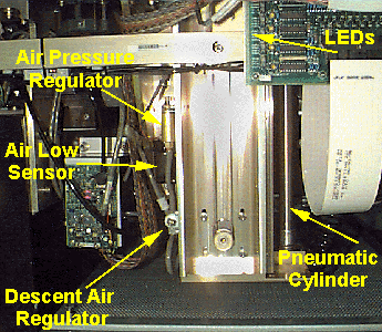
Helps the robot Z motor move the robot and T-bar assembly smoothly in both directions.
Vacuum Venturi 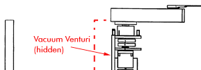
Provides vacuum pressure to the tines of the end effector's forks.
The robot Z motor, belt, and pulleys move the robot with a pneumatic assist. The T-bar assembly (which holds the mapping sensors) and the robot Z assembly utilize air pressure to enable the robot to move smoothly in both directions. If the power or the pneumatics fail, the Z brake is applied. The air low sensor switch on the elevator frame is set to trigger at 40 psi.
The robot Z moves up and down and utilizes two train ponts 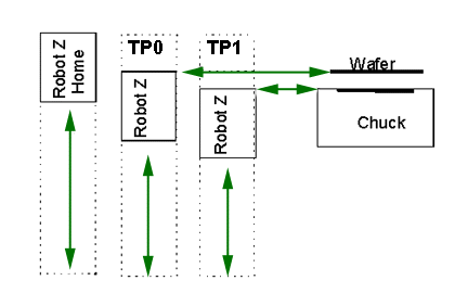 .
.
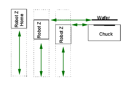
Train point 0: the robot position when wafer is delivered to chuck just prior to loading (wafer will be slightly above chuck)
Train point 1: the robot position when wafer is placed on the chuck, approximately 120 mils below Train Point 0, the end effector forks will be in the cutouts in the chuck.
The robot Z home position is the uppermost position, but home is not a train point.
Verify and Adjust Robot Z Point Setting: To "teach" these moving parts the positions for safe wafer transfer. It also verifies proper functioning of the robot Z sensors. This calibration will be performed in the lab.
Set LED Beam to End Effector Distance: Measures offset between the mapping system beam of light and the end effector. Ensures safe wafer transfer by defining the proper position of the robot Z axis to pick a wafer from a cassette. This calibration will be performed in the lab.
Adjust Robot Z Air Cylinder Pressure: To equalize the force needed to raise and lower the robot Z. (The motor is not strong enough to drive the assembly; it needs air to assist. When the drive belt is removed, the robot should remain stationary; the force of the air holding it up should be equal to the force of gravity pushing it down.) The force is adjusted so that it is equal in both directions. Two adjustments ensure this--one to the air regulator (descent) and one to the air relief valve (air pressure regulator). Both adjustments will be performed in the lab.
 Return to Top
Try to predict the Field Replaceble Units for the Robot Z Assembly. 
What are the train points at the robot Z positions below. Check your understanding by putting the cursor over the position. The Train Point will appear in the gray box at the bottom of your screen.
Return to the "Brain Teaser" in the robot overview section, and add train
point numbers to the Robot Z steps you listed  .
.
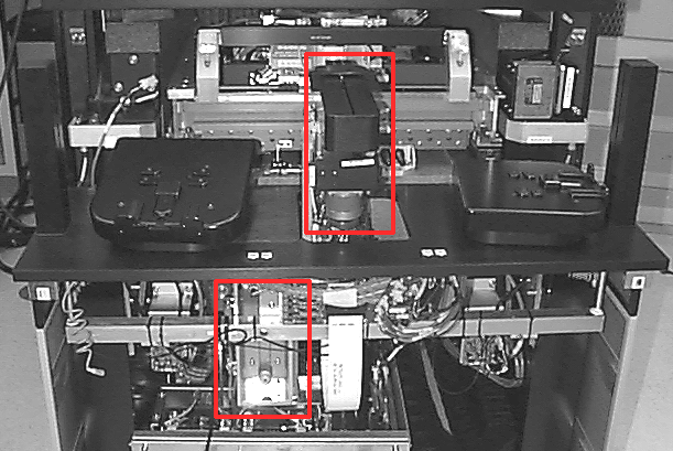
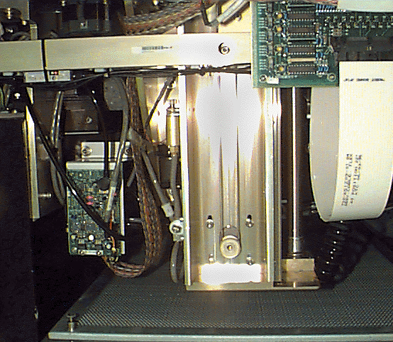
Identify the FRUs visible in the photo below. Check your understanding by putting the cursor over the component. Its name will appear in the gray box at the bottom of your screen.
Return to Top
| The last frame was ==>... | The End Effector |
...and the next frame will be ==>... | The PCBs |
|---|